
ऑटोकैड टिप्स और ट्रिक्स in hindi
ऑटोकैड टिप्स और ट्रिक्स - ड्रा
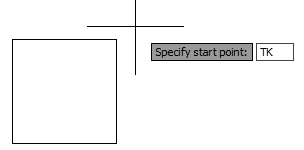
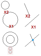
1. एक निर्दिष्ट कोण पर आकर्षित करने के तरीके पुराने और नए टूल का उपयोग करके आप संरेखित रेखाएँ खींच सकते हैं और विभिन्न तरीकों से वस्तुओं को संशोधित कर सकते हैं। @ भाव पुरानी @ अभिव्यक्तियों का उपयोग करना अभी भी ठीक काम करता है, यदि आप उनसे अभ्यस्त हैं। @ रिश्तेदार इनपुट के लिए खड़ा है 1. @ x, y - x और y आपके ड्राइंग में अंतिम निर्दिष्ट बिंदु से x और y दिशाओं में दूरी के लिए खड़े हैं। सकारात्मक या नकारात्मक x और y दिशाओं पर ध्यान दें। 2. @ अस्तित्व <कोण - दूरी मान आपके ड्राइंग में अंतिम निर्दिष्ट बिंदु से सापेक्ष है। सकारात्मक या नकारात्मक कोण दिशाओं पर ध्यान दें। गतिशील इनपुट यदि आप अपने स्टेटस बार पर डायनामिक इनपुट बटन को चालू करते हैं, तो आप @ चरित्र के बिना सापेक्ष x, y और कोण इनपुट टाइप कर सकते हैं। इच्छित इनपुट सक्रिय करने के लिए टैब दबाएँ। ध्रुवीय ट्रैकिंग ध्रुवीय ट्रैकिंग का उपयोग करके आप अपने कर्सर आंदोलन को पूर्वनिर्धारित कोणों में बाधित कर सकते हैं। सटीक कोण दिशा एक लंबी बिंदीदार रेखा और माप कोण द्वारा कल्पना की जाती है। 1. स्थिति पट्टी / ध्रुवीय ट्रैकिंग बटन चालू करें। 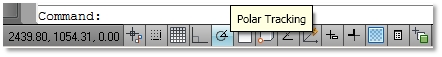 2. पोलर ट्रैकिंग बटन / सेटिंग्स / शॉर्टकट सेटिंग डायलॉग बॉक्स पर शॉर्टकट मेनू 3. ध्रुवीय ट्रैकिंग / सेट एक वृद्धि कोण (कर्सर को इसके कई कोणों पर विवश किया जाएगा) 4. अतिरिक्त कोण - कर्सर केवल दिए गए कोण पर विवश होगा। 5. ध्रुवीय कोण माप / निरपेक्ष (कोण 0 से कोण माप)। 6. ध्रुवीय कोण माप / अंतिम खंड के सापेक्ष (अंतिम खींचे गए खंड के कोण से कोण माप)। 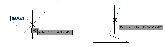 2. निर्माण लाइनों के बिना ड्रा जब आप एक बिंदु को निर्दिष्ट करते हैं जो एक निश्चित दूरी पर एक अलग बिंदु से दूर होता है तो आप क्या करते हैं? कई उपयोगकर्ता एक निर्माण रेखा खींचते हैं और फिर उसके बिंदु पर फिर से शुरू करते हैं। जब पूरा हो जाता है, तो वे निर्माण लाइन मिटा देते हैं। खैर, ऑटोकैड निर्माण लाइनों का उपयोग किए बिना, ऐसा करने के लिए बहुत तेज़ और आसान तरीके प्रदान करता है। ऑब्जेक्ट स्नैप ट्रैकिंग (ओट्रैक) इस फ़ंक्शन का उपयोग करके आप अपने ज्यामिति पर कुछ बिंदुओं को चिह्नित कर सकते हैं और उनके प्रक्षेपण में आकर्षित करना जारी रख सकते हैं। उदाहरण के लिए, आप 2 बिंदुओं को चिह्नित कर सकते हैं और किसी भी निर्माण लाइनों को आकर्षित किए बिना इसके चौराहे बिंदु को खोजने के लिए उनके प्रक्षेपण का अनुसरण कर सकते हैं। ओट्रेक के साथ अंक अंक ऑब्जेक्ट स्नैक्स के साथ संयोजन में काम करता है, इसलिए सुनिश्चित करें कि आप ऑब्जेक्ट स्नैप को चालू और सेट करें। आयत के केंद्र में वृत्त के केंद्र बिंदु को निर्दिष्ट करने के लिए उदा। अगली प्रक्रिया का पालन करें: 1. स्थिति बार / वस्तु स्नैप ट्रैकिंग बटन चालू करें 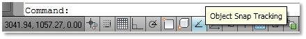 2. स्टेटस बार / ऑब्जेक्ट स्नैप बटन को चालू करें (सेट ऑब्जेक्ट स्नैप्स जिसे आप चिह्नित करना चाहते हैं, जैसे मिडपॉइंट) 3. सर्किल कमांड पर क्लिक करें। 4. इन बिंदुओं पर केवल मँडरा करके आसन्न आयताकार खंडों के मध्य बिंदुओं को चिह्नित करें (उन्हें क्लिक न करें!)। जब एक बिंदु चिह्नित किया जाता है, तो एक क्रॉस साइन दिखाई देगा। इन दो मिडपॉइंट के प्रक्षेपण में अपने कर्सर को उनके चौराहे के करीब ले जाएं। जब आप दो लंबी प्रतिच्छेदन बिंदीदार रेखाएँ देखते हैं, तो एक वृत्त के केंद्र बिंदु पर क्लिक करें। 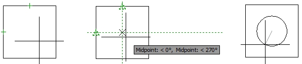 ओट्रैक का उपयोग करके आप एकल सटीक क्षैतिज या ऊर्ध्वाधर दूरी के लिए एक निर्दिष्ट बिंदु से दूर जा सकते हैं। 1. स्टेटस बार / पोलर ट्रैकिंग बटन चालू करें । स्टेटस बार / ऑब्जेक्ट स्नैप बटन चालू करें (जैसे समापन बिंदु) 3. उस बिंदु को चिह्नित करें जिसे आप दूर जाना चाहते हैं। 4. इच्छित दिशा में कर्सर को ले जाएं और सीधे दूरी प्रविष्टि टाइप करें। 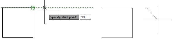 नज़र रखना यदि ओट्रैक केवल एक सटीक क्षैतिज या ऊर्ध्वाधर दूरी के लिए एक निर्दिष्ट बिंदु से दूर जाता है, तो ट्रैकिंग वही करेगा, लेकिन किसी भी संख्या में दूरी के लिए। दुर्भाग्य से ट्रैकिंग एक पुराना फ़ंक्शन है और इसे ऑब्जेक्ट स्नैप मेनू से हटा दिया गया है, लेकिन आप अभी भी किसी भी कमांड के दौरान इसके छोटाकरण टाइप कर सकते हैं। उदाहरण के लिए, क्षैतिज और ऊर्ध्वाधर दोनों दिशाओं में आयत के शीर्ष दाएं कोने से 20 इकाइयों को खींचना शुरू करने के लिए, अगली प्रक्रिया का पालन करें:
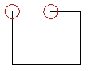
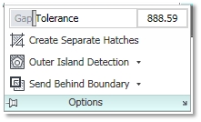
3. पहले ट्रैकिंग बिंदु को निर्दिष्ट करें और आयत के ऊपरी दाएं कोने पर क्लिक करें। 4. कर्सर को क्षैतिज दिशा में ले जाएं और डायरेक्ट डिस्टेंस एंट्री (20 यूनिट) टाइप करें। खंड खींचा नहीं गया है, लेकिन कर्सर निर्दिष्ट दूरी के लिए इंगित दिशा में चला गया है। 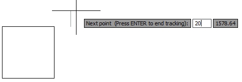 5. कर्सर को ऊर्ध्वाधर दिशा में ले जाएं और सीधी दूरी की प्रविष्टि (20 यूनिट) टाइप करें। सक्रिय ट्रैकिंग फ़ंक्शन के साथ वांछित दिशा में अपने कर्सर को इंगित करना कभी-कभी थोड़ा कठोर हो सकता है। अपनी ड्राइंग में अंतिम बिंदु के करीब रखें या एक दिशा में 0 लंबाई टाइप करें, और शायद आप अपने कर्सर को पुनर्निर्देशित करना आसान पाएंगे। 6. जब आप उस बिंदु तक पहुंच जाते हैं जो आप चाहते थे, तो ट्रैकिंग समाप्त करने के लिए ENTER दबाएँ। 7. पॉलीलाइन कमांड उस बिंदु से सक्रिय रहेगा। 3. त्वरित हैच युक्तियाँ ऑटोकैड 2011 में कुछ नए हैच फीचर्स दिए गए हैं जो हैचिंग प्रक्रिया को तेज कर सकते हैं, और कुछ उपयोगी पुराने भी हैं जिनका उपयोग अक्सर नहीं किया जाता है। एक चरण में रंगीन पृष्ठभूमि के साथ एक हैच पैटर्न बनाएं ऑटोकैड के पिछले संस्करण में ऐसा करने का एकमात्र तरीका एक दूसरे के ऊपर दो अलग-अलग हैच (पैटर्न और ठोस) खींचना था, और फिर ठोस को वापस भेजना था। ऑटोकैड 2011 में यह एक चरण में किया जा सकता है।  1. रिबन / होम टैब / ड्रा पैनल / हैच 2. प्रासंगिक रिबन हैच क्रिएशन टैब / पैटर्न पैनल / एक पैटर्न का चयन करें। 3. गुण टैब / पृष्ठभूमि रंग ड्रॉप-डाउन मेनू / एक पृष्ठभूमि रंग का चयन करें। 4. मानक हैच प्रक्रिया का उपयोग करके किसी ऑब्जेक्ट पर हैच लागू करें। एक बार में सभी अन्य वस्तुओं के पीछे सभी हैच प्रदर्शित करें ऑटोकैड 2011 से पहले आपको प्रत्येक चयनित हैच और नए लोगों को भी वापस भेजना था। अब, आपको केवल एक क्लिक की आवश्यकता है अपने ड्राइंग में सभी हैच भेजने के लिए और नए को वापस करने के लिए। रिबन / होम टैब / पैनल संशोधित करें / ऑर्डर ड्रॉप-डाउन मेनू / बैक करने के लिए हैच भेजें नॉन-बंद ऑब्जेक्ट्स को हैच करें किसी ऑब्जेक्ट को सफलतापूर्वक हैच करने का पहला नियम यह है कि उसकी सीमा बंद है। अन्य मामलों में आपको एक चेतावनी मिलती है कि एक बंद सीमा निर्धारित नहीं की जा सकती है। ऑटोकैड 2010 से पहले आपको शायद छोटे अंतराल को खोजने और सीमा तय करने में एक कठिन समय था ताकि यह सफल हैचिंग के लिए पूरी तरह से बंद हो। यह बाद के संस्करणों में आसान हो जाता है क्योंकि हैच कमांड विफल होने के बाद सीमा अंतराल अस्थायी रूप से लाल हलकों में दिखाए जाते हैं। ठीक है, तो आप जल्दी से एक अंतर पा सकते हैं और इसे ठीक कर सकते हैं। लेकिन बहुत से उपयोगकर्ताओं को पता नहीं है कि एक गैर-बंद सीमा को इसके अंतराल को ठीक किए बिना ही रचा जा सकता है। गैप टॉलरेंस सीमा अंतराल के अधिकतम आकार को अनदेखा करने के लिए निर्दिष्ट करता है या यदि बढ़ाया जाता है, तो वे सीमा को बंद कर देंगे।
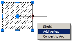
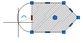
सहयोगी हैच को संशोधित करें जब आप इसकी सीमाओं को संशोधित करेंगे तो सहयोगी हैच स्वचालित रूप से अपडेट हो जाएगा। हैच बनाते समय सहयोगीता को चालू करना चाहिए। 1. रिबन / होम टैब / ड्रा पैनल / हैच 2. प्रासंगिक रिबन हैच क्रिएशन टैब / विकल्प / सहयोगी गैर-सहयोगी हैच को संशोधित करें यदि आप एक हैच बनाते समय सहक्रियाशीलता को चालू करना भूल गए हैं या आपने इसकी सीमा को मिटा दिया है, तो आप अभी भी सहज ज्ञान युक्त ग्रिप का उपयोग करके इसे फिर से खोल सकते हैं। कुछ लोग इसे मिटाने की तुलना में तेज़ तरीका मान सकते हैं, नई सीमा खींच सकते हैं और इसे फिर से पा सकते हैं। 1. अपने ड्राइंग में एक गैर-सहयोगी हैच का चयन करें। 2. शॉर्टकट मेनू में सभी संशोधित विकल्पों को देखने के लिए एक पकड़ पर होवर करें: स्ट्रेच वर्टेक्स, वर्टेक्स जोड़ें और वर्टेक्स निकालें। आप सेंटर ग्रिप्स को आर्क या बैक टू लाइन में भी बदल सकते हैं। 3. एक विकल्प चुनें, उदाहरण के लिए वर्टेक्स जोड़ें। 4. एक अलग स्थान पर लेफ्ट क्लिक नए वर्टेक्स।
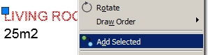
बड़े चित्र में हैच पूर्वावलोकन बंद करें ऑटोकैड 2011 में ´पिक पॉइंट in विधि का उपयोग करके बंद सीमाओं पर मंडराते समय स्वचालित हैच पूर्वावलोकन काफी व्यावहारिक हो सकता है। हालाँकि, बड़े रेखाचित्रों में यह आपकी प्रक्रिया को धीमा कर सकता है क्योंकि आप अपनी ड्राइंग सीमा तक पहुंचने के लिए कई बंद क्षेत्रों पर मंडरा सकते हैं और हर हैच पूर्वावलोकन आपको अपने रास्ते में रोक देता है। यदि आप चाहें, तो आप अपने स्वचालित हैच पूर्वावलोकन को बंद कर सकते हैं। सिस्टम चर HPQUICKPREVIEW 0 पर सेट करें। अतिरिक्त टिप: यदि आप अपने स्वचालित पूर्वावलोकन को बंद कर देते हैं, तो एक प्राप्त करने का एकमात्र तरीका पुराने हैच और ग्रेडर संवाद बॉक्स का उपयोग करके हैच सेटिंग्स निर्धारित करना है। रिबन पर हैच आइकन इस पुराने डायलॉग बॉक्स को लॉन्च करेगा, यदि आप सिस्टम चर HPDLGMODE को 1 पर सेट करते हैं (नए संदर्भ रिबन हैच क्रिएशन को लॉन्च करने के लिए इसे 2 पर सेट करें)। 4. दो या तीन वस्तुओं के लिए एक विशिष्ट त्रिज्या स्पर्शरेखा के साथ एक चक्र बनाना कई उपयोगकर्ता दो अन्य सर्कल में एक वृत्त स्पर्शरेखा आकर्षित करने के तरीके के साथ संघर्ष करते हैं। ज्यामिति की गणना करना और निर्माण लाइनों को खींचने में बहुत समय लग सकता है, खासकर जब ऐसा करने के लिए पहले से ही एक कमांड उपलब्ध हो। खैर, यह थोड़ा छिपा हुआ है। 1. रिबन / होम टैब / ड्रा पैनल / सर्कल ड्रॉप-डाउन मेनू / टैन, टैन, त्रिज्या 2. पहले सर्कल के स्पर्शरेखा के पास क्लिक करें (स्पर्शरेखा तस्वीर स्वचालित रूप से स्विच हो जाएगी) 3. दूसरे सर्कल के स्पर्शरेखा के पास क्लिक करें। 4. नए सर्कल की अनुशंसित त्रिज्या की पुष्टि करने के लिए एंटर दबाएं या अपना खुद का टाइप करें। यदि आप तीन ऑब्जेक्ट्स के लिए एक वृत्त स्पर्शरेखा बनाना चाहते हैं, तो सर्कल ड्रॉप-डाउन मेनू से टैन, टैन, टैन कमांड पर क्लिक करें। 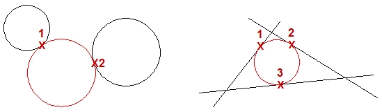 5. चयनित वस्तु के समान वस्तु का तेजी से निर्माण किसी ऑब्जेक्ट को खींचने का एक शास्त्रीय तरीका जो आपके ड्राइंग में एक या समान है, वह पहले सही लेयर को सक्रिय करना होगा, फिर शायद सही टेक्स्ट या डाइमेंशन स्टाइल को करंट बनाने के लिए, और फिर अंत में राइट कमांड का उपयोग करना होगा। खैर, ऑटोकैड 2011 में यह सब एक ही चरण में किया जा सकता है। Add चयनित कमांड उस कमांड को लॉन्च करता है, जिसे उसके परिभाषित गुणों के साथ एक चयनित ऑब्जेक्ट बनाने के लिए आवश्यक था। 1. अपने ड्राइंग में एक ऑब्जेक्ट का चयन करें, उदाहरण के लिए पाठ। 2. अपने ड्राइंग क्षेत्र पर शॉर्टकट मेनू / चयनित जोड़ें। 3. चयनित पाठ को आकर्षित करने के लिए प्रयुक्त कमांड को लॉन्च किया जाता है, जैसे कि बहु-पाठ पाठ। 4. नए पाठ में वही गुण होंगे जो चयनित हैं, उदाहरण के लिए समान परत, पाठ गुण, आदि।
6. पैरामीट्रिक ड्रािंग्स अधिक सटीक और संशोधित करने में आसान हैं पैरामीटर ड्राइंग को ऑटोकैड 2010 में पेश किया गया है और यह कवर करने के लिए काफी बड़ा विषय है। सामान्य तौर पर, इसका मतलब है कि आप संशोधित होने के बाद अपने ज्यामितीय और आयामी संबंध को स्थापित करने और बनाए रखने के लिए अपनी ज्यामिति को बाध्य कर सकते हैं। परिणामस्वरूप आपको तेजी से संशोधन और कम त्रुटियों के साथ एक स्वचालित ड्राइंग मिलती है। यद्यपि बड़े रेखांकन में पूरी ज्यामिति को बाधित करना व्यावहारिक रूप से असंभव है, आपको कुछ ड्राइंग खंडों की मदद करने के लिए एक उपयोगी उपकरण के रूप में मिल सकता है। 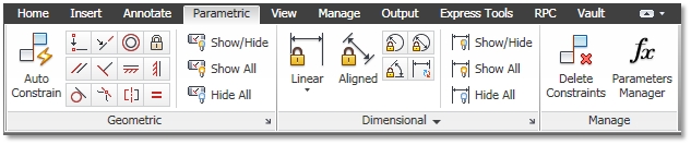 ज्यामितीय अवरोध आप ज्यामितीय रूप से वस्तुओं को दबा सकते हैं, वस्तुओं या वस्तुओं पर सिस्टम को समन्वित करने के लिए महत्वपूर्ण बिंदु, उदाहरण के लिए, आप यह परिभाषित कर सकते हैं कि दो रेखाएं हमेशा एक-दूसरे के लिए लंबवत होती हैं, दो वृत्त संकेंद्रित, दो रेखाएं समान लंबाई, आदि। आपके चित्र में प्रत्येक बाधा का अपना अवरोध होता है। बार आइकन, ताकि आप उन्हें आसानी से पहचान सकें। आप ज्यामितीय बाधाओं को स्वचालित रूप से या मैन्युअल रूप से ज्यामिति को असाइन कर सकते हैं।
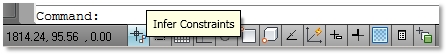
स्वचालित ज्यामितीय बाधाएँ ज्यामितीय बाधाओं को स्वचालित रूप से लागू करने के दो तरीके हैं: - ज्यामिति बनाते और संपादित करते समय ज्यामितीय बाधाओं को लागू करें: 1. स्थिति पट्टी / इनफेर बटन को चालू करें
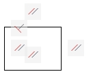
- वस्तु चयन के लिए ज्यामितीय बाधाओं को लागू करें: 1. रिबन / पैरामीटर टैब / ज्यामितीय पैनल / ऑटो बाधा 2. बाधा सेटिंग्स संवाद बॉक्स खोलने के लिए सेटिंग्स [एस] विकल्प निर्दिष्ट करें। 3. लागू होने के लिए आदेश और बाधाओं के प्रकार का निर्धारण करें। 4. स्वचालित रूप से बाधा डालने के लिए वस्तुओं का चयन करें। 5. एक दूसरे के सापेक्ष चयनित वस्तुओं के उन्मुखीकरण के आधार पर बाधाओं को लागू किया जाता है। 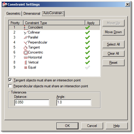 आयामी बाधाओं आयामी बाधाएं आपके आरेखण के आकार और अनुपात को नियंत्रित करती हैं। वे नियमित आयाम लाइनों के समान लगते हैं। हालाँकि, यदि आयाम रेखाओं को उसके आयामित वस्तु द्वारा नियंत्रित किया जाता है, तो एक विवश वस्तु को उसके आयामी अवरोध द्वारा नियंत्रित किया जाएगा। आप वस्तुओं या दो बिंदुओं के बीच की दूरी और वस्तुओं पर कोणों या वस्तुओं पर दो बिंदुओं के बीच की दूरी पर आयामी बाधाएं लागू कर सकते हैं। आप त्रिज्या और सर्कल के व्यास और व्यास को भी नियंत्रित कर सकते हैं। आयत के दोनों किनारों पर आयामी अवरोधों को लागू करें: 1. रिबन / पैरामीटर टैब / आयामी पैनल / रैखिक 2. ऑब्जेक्ट निर्दिष्ट करें [O] विकल्प / आयत के एक खंड का चयन करें 3. आयाम रेखा स्थान निर्दिष्ट करें। 4. आयामी बाधा के नाम की पुष्टि करने के लिए, जैसे d1 =, Enter दबाएं। अन्यथा अपना नाम और एक समान चिह्न टाइप करें, जैसे A =, और फिर Enter दबाएँ। 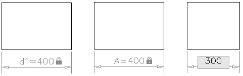 आयामी बाधाओं के माध्यम से नियंत्रण ज्यामिति आकार: 1. इसे सक्रिय करने के लिए आयामी बाधा के मूल्य पर डबल क्लिक करें। 2. एक नया मान (300) या सम समीकरण (300/2) लिखें। समीकरण अन्य आयामी बाधाओं (ए = बी * 2) से संबंधित हो सकते हैं। 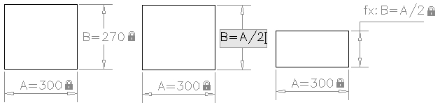 बाधाओं को दिखाएं / छिपाएं और हटाएं कई अड़चनें आपके ड्राइंग को नेत्रहीन रूप से भीड़ सकती हैं। यदि आप उन्हें देखना नहीं चाहते हैं, तो आप उन्हें छिपा सकते हैं। हालाँकि आप उन्हें नहीं देख पाएंगे, फिर भी उन्हें लागू किया जाएगा और वे आपकी ज्यामिति को नियंत्रित करेंगे। आप आसानी से उन्हें फिर से वापस दिखा सकते हैं। लेकिन जब बाधाएं आपकी ज्यामिति के साथ हस्तक्षेप करने लगती हैं तो आप उन्हें स्थायी रूप से हटा भी सकते हैं। Hide constraints: Ribbon / Parametric tab / Geometrical or Dimensional panel / Show/Hide or Hide All. Show constraints: Ribbon / Parametric tab / Geometrical or Dimensional panel / Show/Hide or Show All. Delete constraints: 1. Ribbon / Parametric tab / Manage panel / Delete Constraints 2. Select objects with constraints you want to remove permanently. 7. Automate Field Data in Your Drawing A field is an updateable text linked to different data of your drawing file, geometry, hyperlinks, etc. The biggest advantage of fields is that they get automatically updated whenever you make some changes. So you can save time and avoid making mistakes as you don’t have to modify the data yourself. Many useful field types are already predefined, meaning that they are ready to insert or attach to your geometry. But the great thing about them is that you can also create and define your own custom fields. Types of Predefined Fields Predefined Fields that you can insert are divided into next Categories: Date&Time Various fields to add date and time stamps to your drawing: CreateDate, Date, PlotDate and SaveDate. Under Date format you can choose several predefined examples of date formats to insert. Document Fields related to working in a document: Author, Comments, Filename, Filesize, HyperlinkBase, Keywords, LastSavedBy, Subject and Title. Field formats correspond to field type. Linked Insert Hyperlinks as quick links to open other documents, drawing views or web pages. Related to: 15. Add Links for a Quick Access to Other Documents, Saved Views and Web Page Objects Display information about selected objects (area, length, etc.), named object types, blockplaceholders and even calculate data using formulas. For example, you can insert a field as an object’s area and when you stretch the same object, the new area will be recalculated automatically. Other Rarely used but available are fields related to System Variables and Diesel-/Lisp-Expressions. Plot Add automatically updated information about a plotted drawing: DeviceName, Login, PageSetupName, PaperSize, PlotDate, PlotOrientation, PlotScale and PlotStyleTable. SheetSet Fields to automate sheet set data. Insert Field Fields can be inserted as a stand-alone text or within a text, attribute, attribute definitions and even in table cells.
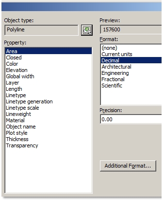
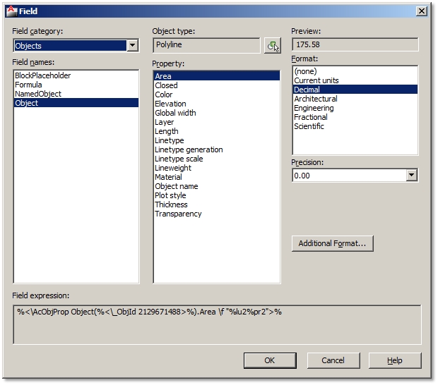 Inserting field within attribute definition When creating, e.g. dynamic blocks you can insert field within an attribute definition. Attribute Definition dialog box / Click Insert Field button instead of typing the default value / Select field. 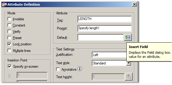 Inserting field in table cells Select a Table cell / Shortcut menu / Insert Field 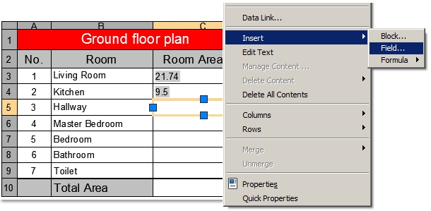 Update Field All inserted fields will be automatically updated after you make changes to your drawing file or geometry. You can control which and when field data gets updated by setting FIELDEVAL system variable. You can set the following controls: 0 = not updated 1= updated on Open 2= updated on Save 4= updated on Plot 8= updated on use of Etransmit 16= updated on regeneration Default value is set to 31, which is the sum of all updated values; therefore all of them are active. So when you, e.g. stretch an object with an area field definition, just type RE (short for Regen command) and new area field value will be updated. Modify Fields Field definitions can be modified after field has been inserted in your drawing, e.g. modifying broken links or assigning length object property field instead of area. When a field link gets broken, you will notice a ### sign instead of the field value. You can modify fields following next steps: Modify a stand-alone field or field within a text Both of them can be modified the same way as a standalone field is actually a multiline text field. 1. Double-click on inserted field to activate Text Editor. 2. Select field to highlight it / Shortcut menu / Edit Field 3. Choose different field options. 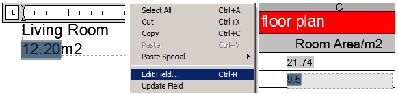 Modify field in a table cell 1. Double-click a cell with inserted field to activate it 2. Select field to highlight it / Shortcut menu / Edit Field 3. Choose different field options. If a field text displays these characters - - - it means that the required information of the inserted field is still unknown. For example, inserted SaveDate field will display these signs until you save the drawing. Format Fields Field text format style depends on the active Text Style when inserting a field. You can always change its text properties after it’s already been inserted like you do with normal text (Properties palette or Text Editor). Field format in the Field dialog box usually corresponds to a chosen field name. For example, you can choose from many date formats or options to display a file name. However, fields which are linked to geometry, e.g. length or area of an object, have some additional formatting options. Let’s say your object area field is displayed in squared centimeter units, but you would like to display it in squared meters units:
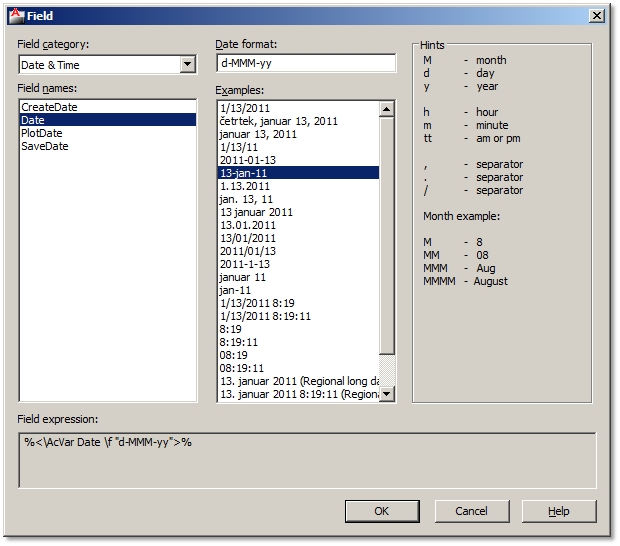
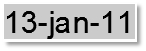
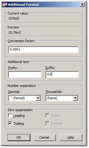
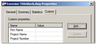
Format options in Additional Format dialog box: 1. Field dialog box / Additional format button / Additional Format dialog box 2. Conversion factor – specify conversion factor to use on the current value, e.g. 0.0001 (1cm2 = 0.0001m2). 3. Prefix – specifies prefix to be added in front of the current value. 4. Suffix – specifies suffix to be added at the end of the current value, e.g. m2. 5. Number separators – specifies a decimal separator and the formatting for numbers over 1000. 6. Zero suppression – suppression of leading (0.100 = .100) and trailing (0.100 = 0.1) zeros in decimal values or of feet (0'-3 1/2" = 3 1/2") and inches (3'-0" = 3') with a zero value. If you copy and modify a field, you will have set additional formatting all over again. Field values or texts have a gray background color so that you can easily recognize them in your drawing. Gray shade will not be plotted, but if it bothers you anyway, you can turn it off by setting FIELDDISPLAY system variable to 0.  Create and Insert a Custom Field All custom drawing properties can be inserted as fields from the Document field category. Create a custom field 1. File / Drawing Properties / Custom tab 2. Add button / Specify Custom property name, e.g. Project name / Ok / Ok 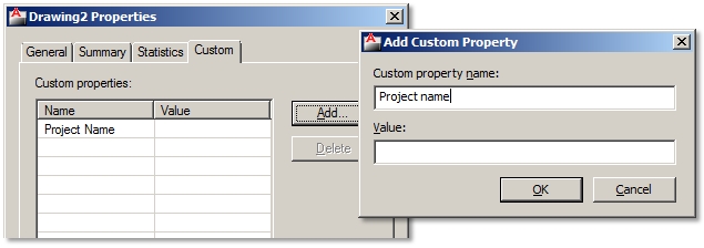 Insert a custom field 1. Ribbon / Insert tab / Data panel / Field 2. Field Category options / Document 3. Field names / Project name 4. Format / Uppercase 5. Specify field insertion point 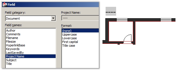 Modify a custom field 1. File / Drawing Properties / Custom tab 2. Click Value cell of the Project name / Enter the name of Project name, e.g. Familiy House / Ok 3. Regenerate drawing (RE). 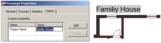 You can use the same procedure to create many custom fields. 8. Create Automatic Title Blocks It can be quite annoying to change the same data in many title blocks in your drawing when it needs to be updated. Therefore it is best to organize or create them in a way that you will change data only once and the rest of the common data will update automatically. A title block should be created using the following objects: - Table geometry (black color). - Text to describe inputs (black color). - Attributes to specify single drawing properties, e.g. drawing name or number (red color). - Fields to specify project data which is common to many drawings, e.g. project’s or investor’s name (blue color). Table Geometry and Text Descriptions 1. Open a new drawing. 2. Draw table geometry, e.g. Polyline. 3. Use Multiline or Single Line Text to add description of inputs. 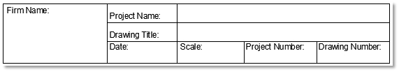 Create and Insert Attributes Ribbon / Home tab / Block drop-down panel / Define Attributes Create and insert 3 types of attributes each at a time: 1. Drawing title: Tag (DWG-TITLE), Prompt (Specify drawing title!), Justification (Left) 2. Scale: Tag (SCALE), Prompt (Specify drawing’s scale!), Justification (Right) 3. Drawing number: Tag (DWG-NUMBER), Prompt (Specify drawing’s number!), Justification (Right) 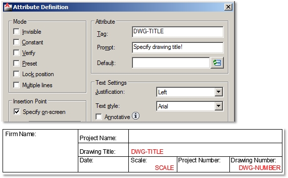 Insert Predefined Date and File Name Fields Insert date as a predefined field: 1. Ribbon / Insert tab / Data panel / Field 2. Field Category options / Date&Time 3. Field names / Date 4. Examples / Select the date format / Ok 5. Specify field insertion point. Insert file name as a predefined field: 1. Ribbon / Insert tab / Data panel / Field 2. Field Category options / Document 3. Field names / Filename 4. Format / Filename only / Ok 5. Specify field insertion point. 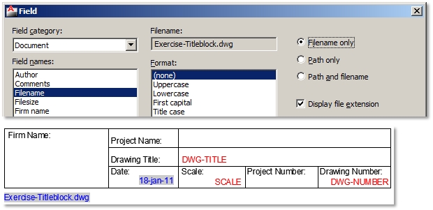 Create and Insert Custom Fields
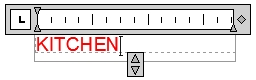
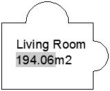
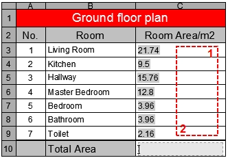
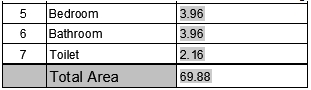
Insert a custom field 1. Ribbon / Insert tab / Data panel / Field 2. Field Category options / Document 3. Field names / Firm name 6. Format / Uppercase 7. Specify field insertion point. 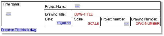 Because the custom filed data isn’t yet filled out in the Drawing Properties dialog box, field text displays as characters - - -. If you decide to use custom fields as drawing properties in your title block, make sure, that the same drawing properties are also specified in the drawing into which you will insert this title block. So, to avoid typing and re-creating custom fields as drawing properties in each drawing with inserted title block, it is advisable to save custom drawing properties, thereby custom title block’s fields in a drawing template (.DWT). If you use the same drawing template to start of your projects, then custom fields in inserted title block will work just fine (links won’t be broken). Insert Title Block as a Block If you drew your own title block in a new drawing, just save it and you will be able to insert it in any other drawing as a block. Before you do that, make sure you don’t forget to specify title blocks base point. 1. Type BASE. 2. Specify base point, e.g. bottom right corner. 3. Save title block .DWG file. Open your project drawing and insert a title block. 1. Ribbon / Home tab / Block panel / Insert 2. Browse for title block file. 3. Specify insertion point of title block. Fill out the data in title block: 1. Edit Attributes dialog box will automatically open after specifying insertion point. Fill out attribute data. 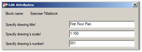 2. File / Drawing Properties / Custom tab 3. Click Value cells to fill out custom field title block data. 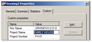 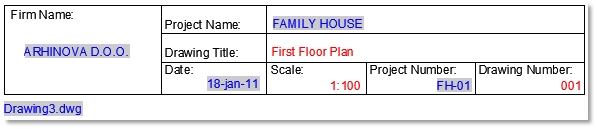 Modify the data in title blocks: You can change different attribute data in the same title blocks in a drawing. Double click any object of the title block and change data in Enhanced Attribute Editor dialog box. Custom field data is changed only once in the Drawing Properties dialog box. The same custom fields in all title blocks will update. Extra tip: If Edit Attributes dialog box doesn’t open, and you are prompted to fill out attribute data at command lines, the set ATTDIA system variable to 1. This will turn on the display of attribute dialog box. 9. Automate Length or Area Calculations Objects´ area or lengths are often used in different calculations, like area calculations, etc. As plans get modified and object dimensions change you’d normally have to recalculate all area calculations and change data in your drawing. Wouldn’t it be great, if you just stretched a room in your drawing and the following data automatically updates? - Room’s area size in your room description, - Room’s area size in the floor plan area calculations table, - Total area calculation in the floor plan area calculations table. Insert Fields in Room Area Descriptions 1. Draw closed boundaries of all room areas with polylines. 2. Ribbon / Home tab / Annotation panel / Multiline Text 3. Specify text bounding box and type in any text, e.g. Living Room, and press Enter to the next line. 4. Shortcut menu / Insert Field 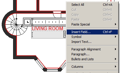 5. Field Category options / Objects 6. Field names / Objects 7. Object type / Select Object button 8. Select a closed boundary of the living room area in a drawing. 9. Property / Area 10. Format – choose your unit format and precision 11. Additional format button – additional formatting options only / Ok / Ok 12. Type suffix for squared units ´m2´. 13. Close Text Editor. Insert area fields for all other room area descriptions. You can also copy the one you’ve created to other rooms, but you will have to modify area fields to link proper rooms to their area boundaries. Insert Fields in the Floor Plan Calculations Table Using Table command design and insert your own table. Activate cells to normally type in text, e.g. Living room. Room areas must be inserted as fields linked to closed room boundaries. 1. Click the table cell where you want to insert room area. 2. Shortcut menu / Insert / Field 3. Field Category options / Objects 4. Field names / Objects 5. Object type / Select Object button 6. Select a closed boundary of the living room area in a drawing. 7. Property / Area 8. Format – choose your unit format and precision 9. Additional format button – additional formatting options only / Ok / Ok Repeat the procedure for all room areas. 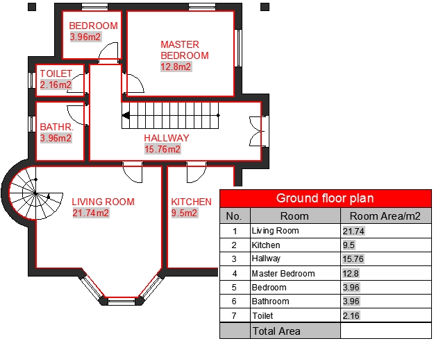 Create Field Formulas to Calculate the Table Data Data in tables can be calculated using field formulas. For example, to calculate the total of all room areas: 1. Click the table cell where you want to insert the total room area. 2. Shortcut menu / Insert / Field 3. Field Category options / Object 4. Object type / Formula 5. Select Sum button. 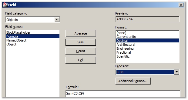
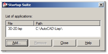
Modify Room Size in Your Drawing and Update All Area Calculations If you stretch some room sizes and regenerate the drawing (RE), all fields linked to stretched room boundaries will recalculate their area data. 10. Use Object Snap to Copy Geometry from PDF Files You can use a PDF file as an underlay in your drawing and use object snaps to quickly draw on it. 1. Select the outer frame of your inserted PDF underlay. 2. Contextual ribbon PDF Underlay tab / Options panel / Turn on Enable Snap 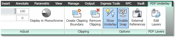 3. Status Bar / Turn on Object Snap button / Select object snaps 4. Use Draw commands to draw across your PDF underlay using object snaps. 11. What AutoCAD Can´t Do, Lisp Applications Can The great thing about AutoCAD is that it supports different applications to the program. Some are complex and probably cost a lot of money, but you can also find a lot of simple free Lisp plug-ins that can help you speed up or simplify some operations. You can find a whole lot on the internet. Download Lisp File 1. Create a folder on your hard drive to store all AutoCAD Lisp files in the future, e.g. C:\AutoCAD\Lisp. 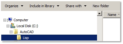 2. Browse the internet for a lisp file (.LSP). Try browsing entries like: AutoCAD free lisp (you might also add short descriptions of an AutoCAD operation you seek for). 3. Download the lisp file from the internet to your, e.g. C:\AutoCAD\Lisp, on your hard drive. 4. If the downloaded file is saved in .TXT file format, rename its file extension to .LSP. The reason why some Lisp applications are saved in .TXT file format is because they are programmed and saved as text files. Authors also usually add some description of their application and maybe even installing instructions. So, reading Lisp file in .TXT format file can provide you some valuable information. You just rename file extensions to change one file type to another. However, if you want the application to work in AutoCAD, the file must have an .LSP file extension. Add Support File Search Path in AutoCAD to Your Lisp File 1. Tools / Options / Files tab 2. Click + sign in front of Support File Search Path list 3. Click Add button / Click Browse button / Browse for folder with stored Lisp files, e.g. C:\AutoCAD\Lisp. 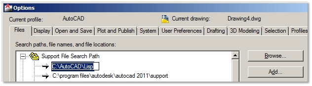 Load Lisp Application 1. Tools / Load Application 2. Load/Unload Applications dialog box / Browse and select your Lisp file / Click Load button / Close 3. Lisp application is launched by typing usually its program name at command lines. Otherwise check on the internet where you downloaded your lisp file from, and see if author specified a launching command. You can also change .LSP file to .TXT file, open text file, and see if author wrote it down. 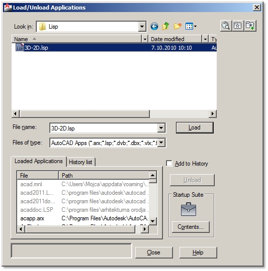 Load Applications Automatically Every Time You Launch AutoCAD Normally you will have to load applications in every new drawing. If you want to skip this process, simply set to load applications every time you launch AutoCAD.
|


Comments
Post a Comment